Photo Tour of Magnolia Observatory
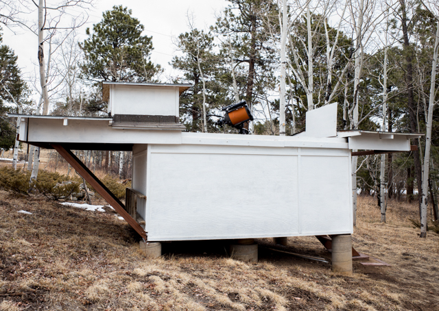
Magnolia Observatory is located in Boulder County, Colorado USA at 8350 feet (2500 meters) above sea level. The observatory is a thin-walled wooden box having a wooden floor which is 8x12 feet, and the walls are four feet high. The box is perched one to three feet above the sloping mountainside atop four concrete posts. Each post sits on a rectangular concrete footing three feet below ground level. The roof has a cupola over the telescope pedestal, and the roof splits to roll off with the two portions moving in opposite directions. The walls are four feet high to afford a good view of the sky and of the area surrounding the building.
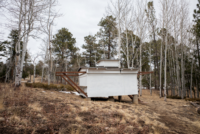
The telescope pedestal also begins three feet below ground level with a rectangular concrete footer two feet on a side. From this footer, an 18 inch concrete pedestal rises to just below the floor where it is reduced to a 12 inch diameter. This column then rises through a hole in the floor and for about three feet more. A gap between the column and the floor mechanically isolates the pedestal and prevents any vibrations of the building from coupling to the column and thence to the telescope.
The observatory was originally constructed in 1978-79. It was built to house an orange-tube Celestron C8 on its fork mount, and the pedestal was placed off center toward the south wall, since working near the celestial pole is awkward for fork-mounted telescopes like the C8. The off-center placement also facilitates convenient placement of shelves, cabinets and miscellaneous storage in the small building. The pedestal is centered along the long axis of the building.
The observatory still houses the C8 SCT, but now it rides on a Losmandy G11 German equatorial mount which is controlled by a Gemini II dedicated computer in response to commands received from a Gemini hand control, or from the house computer over ethernet or from the observatory computer via ethernet or USB or both. Several other pieces of equipment are now in use, too. The mount and its controller are provided with 12V and are linked to the observatory computer via both ethernet and USB.
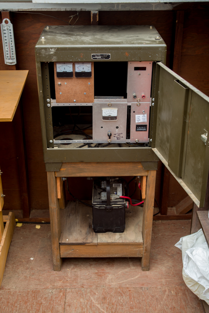
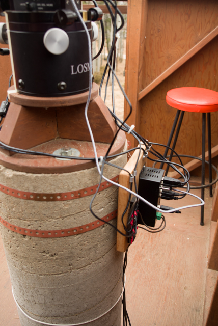
Electrical power for the observatory is supplied by 12V lead-acid batteries under the instrument cabinet. The brown control panel in the cabinet switches the 12V supply on and off and measures the voltage and the amperage being used. The other panels in the cabinet provide the power control and tracking rate control for the C8's original fork mount.
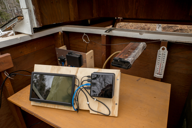
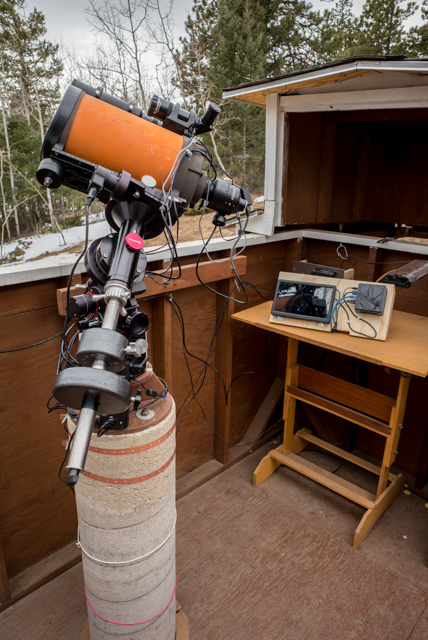
The observatory computer, an Intel NUC mini computer, is the rectangular box on the foreground panel which also includes a small display. A bluetooth keyboard and mouse can be added to the table and used to operate all the equipment from inside the observatory. Distribution of power and data is provided by the smaller panel at the rear of the table. Behind that panel are the converters that convert the 12V supply to the 19V and 24V supplies that observatory computer and the WiFi radio requiree, and also houses terminal blocks for distributing power. The large box on the front is an ethernet switch, while the small one is a power-over-ethernet adapter for the ethernet/WiFi radio link which communicates with the house to enable remote control of all of the equipment from there, mostly working through the observatory computer.
There are three principal different use cases for the C8: visual, general photography camera and photometry camera. These are attached as desired to the C8 behind two pieces of (optional) auxiliary equipment. The first is a Celestron 0.63x field flattener/focal reducer, and the second is a Baader-Planetarium Steeltrack II precision focuser along with its SteelDrive motor control. The focuser ends in a T-thread which provides a single attachment method for all three use cases. Here a visual back, a diagonal and an eyepiece are attached.The focus motor is provided with 12V and is controlled via USB through its own hand control. Balancing the mount requires that the small counterweight on the counterweight bar be set at the spot marked for that use case to balance in Right Ascension, and also that the the entire telescope and attached equipment must be shifted in the mount's saddle to balance in Declination. Balancing is very important to let the stepper motors which move the mount operate effectively.
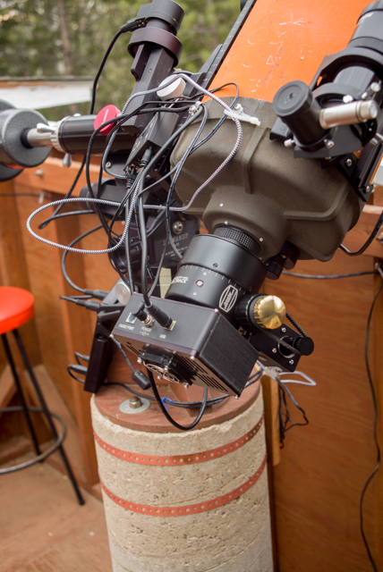
This photo shows the C8 as set up for visual use. All of the equipment attached to the C8 can be seen: the knurled cylinder next to the C8 is the field flattener, the large cylinder with the gold knob is the focuser which is connected to the focuser motor via a timing belt which is looped around the focusing shaft behind the gold knob. (This can be seen better in the next photo.) The hand control for the focuser is often used for visual work and it is shown here looped over the focusing knob in the photo.
This photo shows the C8 when set up for photometry. The camera is a SBIG ST-402ME camera having an internal filter wheel that carries B,V and I photometry filters as well as an unfiltered Clear aperture. That photometry wheel can be switched with a second filter wheel that carries standard R, G and B filters for making standard color-separated photos. The camera includes a thermoelectric cooler capable of reducing the camera chip's temperature by as much as 30 °C below ambient in order to facilitate low thermal noise in images made with long exposures. The camera is provided with 12V and is controlled via USB. With this camera installed, the telescope with all attached equipment comes to about 30 pounds, a consevative half of the maximum that a G11 mount is capable of handling.
A Nikon D600 DSLR or other standard digital camera can be also attached to make general photos that cover a much wideer field of view than the photometry camera covers.
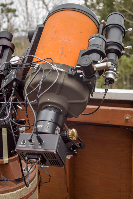
This photo also shows the two small telescopes that are attached to the C8. At the left is a Celestron 9x50 finder telescope having a 5° field of view and dual crosshairs that are illuminated via small batteries. To the right is a 60 mm f/4 guide telescope together with a QHY5L-II CMOS camera. The camera receives both power and data over its USB connection, and the observatory computer can run a guiding program that uses the camera to follow a star on the camera's sensor and then to calculate any necessary commands and send them to the Gemini computer to keep the telescope pointed in a fixed direction during long exposures.
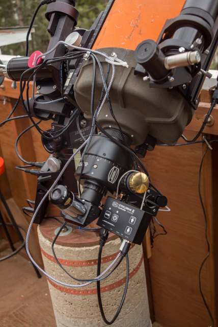
There are only three cables which run to the pedestal: 12V, USB and ethernet. This photo attempts to show where they go when they reach the pedestal. The 12V goes to a power distribution terminal block and from there individual cables go to the other instruments that need a 12V supply: the USB hub, the Gemini II and mount, the ST-402ME camera/wheel and the focuser motor. The USB cable goes to the USB hub where the USB signals for the different instruments are repowered and then sent over individual cables to their destinations: the Gemini II and mount, the ST-402ME camera/wheel, the focuser motor, the QHY5L_II camera and the Nikon D600 or Leica M8 camera. The ethernet cable goes directly to the Gemini II and mount.
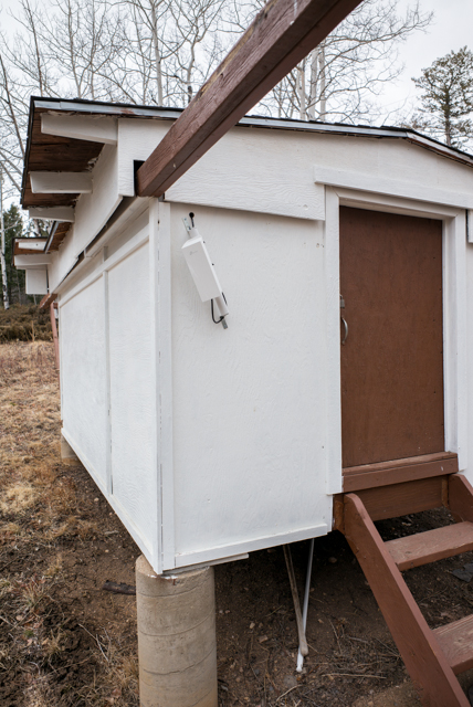
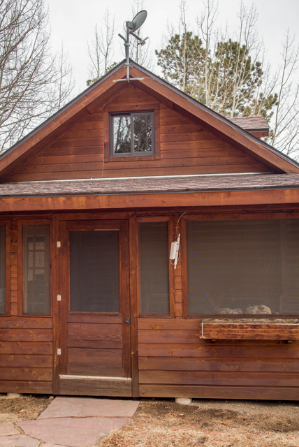
The small white boxes in these photos are the ethernet/WiFi radio links between the observatory and the house. They are a pair of TP-Link CPE200 WiFi radios. The one attached to the outside observatory wall receives both power-over-ethernet and data via an ethernet cable from the ethernet switch via a POE adapter. The radio at the house is fastened to the outside wall of the screened porch, and a cable leads through the walls of the porch and then of the house and into the study where it feeds through a POE adapter and then to the LinkSys router that controls the local network. The router also provides an internet connection via the antenna seen at the top of the gable at the end of the house, so the internet is accessible from both the house and the observatory.
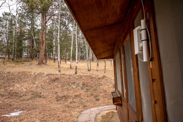
This photo shows the view toward the observatory from the house. The observatory, some 300 feet up the mountain from the house, can just be glimpsed as the white form behind some small tree trunks about halfway from the center of the photo's left edge to the nearest big pine tree. There is enough clear space through those intervening trees that the WiFi radio signal is transmitted with good fidelity and bandwidth.
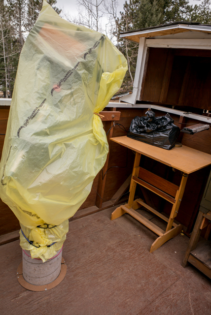
Magnolia Observatory's roof must be opened and closed manually. That makes it less than completely remote. However, that would not be possible anyway as the equipment must also be covered when not in use, and doing that remotely would be very difficult to accomplish well. It must be covered, because otherwise insects would infest the equipment during warm weather, and because sometimes dust drifts over and into the observatory from a nearby residential sideroad, and I prefer not to engage in constant recleaning were it to be left covered. The yellow cover over the pedestal is closed tightly at its bottom with bungee cords to keep out the bugs.